紅外線開關(guān)電路

紅外線開關(guān)電路-Infra Red Switch
本文引用地址:http://www.antipu.com.cn/article/163327.htmThis is a single channel (on / off) universal switch that may be used with any Infra Red remote control that uses wavelengths between 850-950nm.
Notes:
Any button of any remote control may be used to work this universal switch. The button must be pressed for two seconds (determined by R3 and C2) before the relay will operate. Once operated the circuit will remain in this state (latched) until reset. To reset, any button is pressed and held for the delay.
For example, if you were watching TV, and your set was tuned to Channel 3, you could press and hold the TV remote controls channel 3 button for two seconds. That way the TV viewing would not be affected and the relay would activate. You can connect anything to the relay, for example a lamp, but make sure that the relay contacts can handle the rated voltage and current.
Circuit Operation:
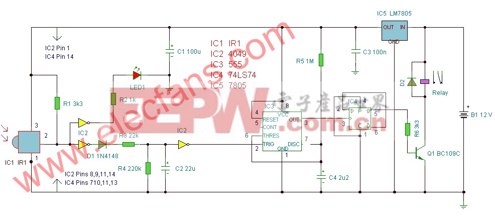
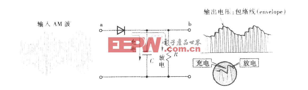
IC1 is an Infra Red module. IR modulated pulses are received and buffered by this IC. It has a standard TTL output, the output with no signal is logic 1. One gate of a CMOS inverter and drives Red LED1 as a visible switching aid. Another gate buffers the signal and applies it to the time constant circuit, comprising R3,C2,R4 and D1. C2 charges via R3, and discharges via R4, D1 prevents quick discharge via the low output impedance of the CMOS buffer.
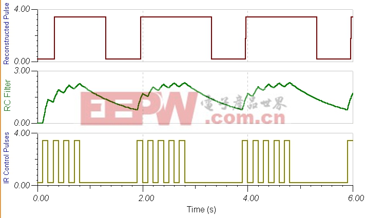
The pulses are further buffered and contain jaggered edges as shown above. These edges are produced by the modulated IR data, which has to be removed. This is achieved using IC3, a 555 timer wired as a monostable, pulse duration R5, C4. These cleanly reconstructs a single clean pulse to activate the bistable latch. A D type flip flop, IC4 is configured as a bistable. The input is applied to the clock pin, the inverted output fed back to the data input and clear and preset lines are tied to ground. For every pulse the relay will operate and latch, the next pulse will turn off the relay and so on. Note that quick turn on and off of the relay is not possible. The output pulse is set at about 1.5 seconds and input delay by R3, C2 set at two seconds.
Parts List:
R1 3k3
R2 1k
R3 22k
R4 220k
R5 1M
R6 3k3
B1 12 V
D1 1N4148
D2 1N4003
Q1 B109
LED1 CQX35A
IC1 IR1 available from Harrison Electronics
IC2 4049
IC3 CA555
IC4 SN74HCT74
IC5 LM7805
Relay 12 Volt coil with changeover contact
C1 100u
C2 22u
C3 100n
C4 2u2

DIY機(jī)械鍵盤相關(guān)社區(qū):機(jī)械鍵盤DIY
紅外遙控器相關(guān)文章:紅外遙控器原理


評論